Guide to build your own miniAstroHeat


Guide to build your own miniAstroHeat

I am excited to announce that the miniAstroHeat DIY project in this post has won the recent contest from Blynk! I would like to express my gratitude to all of you who have shown interest in the project.

I am honoured to have been selected as the winner of this contest in its category and will continue to share my passion for astrophotography and technology with all of you through this blog.

Thank you again for your support and stay tuned for more exciting updates!

1. Introduction

To avoid carrying heavy equipment in and out from my cellar, I needed a way to keep my astrophotography equipment safe and protected from the elements all year round, even during long periods of disuse. While an Arduino-based automatic heating system helped me control dew heaters during photography sessions, it wasn't enough to provide the resilience level of protection I needed.
A single sensor or power failure could leave my gear exposed to moisture and ice for days or even weeks without being noticed.

That's why I set out to build a more comprehensive solution, based on a ESP32 connected to the cloud and controlled by a smartphone app powered by Blynk. This solution would give me the peace of mind I needed to leave my equipment outside safely and securely. If anything goes out of range, I immediately get a notification.

After 2 years of hard work I launched my own product, AstroHeat, the ultimate power box and USB hub for astrophotography equipment, connected to the cloud and controlled with your smartphone.

But I understand that the cost of equipment can sometimes be a barrier to entry for amateur astronomers and astrophotographers. I have been there, so that's why I am offering with this project a DIY option - building a miniAstroHeat with some of the features of the full device.

This step-by-step guide is suitable for all skill levels, with no soldering skills required. We'll be using affordable and easy-to-assemble electronic components, with a free-plan connection to the cloud through Blynk.With miniAstroHeat you can monitor and control the power applied to the dew heaters directly from your smartphone, with two channels and two selectable heating modes (Dew Auto & individual Manual Power).

You can see the list of materials and download the code from this project published at hackster.io

With the information and code provided, you can easily adapt the project to other more advanced configurations.


2. Assembling and wiring the miniAstroHeat

Once you have all the components, connect the different components as per the schematics in the diagram:

When you begin working with the ESP32 module, you may notice that there are no available pin holes to connect the jumper wires from the sensors and MOSFET modules once the module is plugged into the breadboard.To solve this issue, you can use two breadboards and remove one side power panel from each breadboard on opposite sides, creating a "bridge" in the middle.

The ESP32 can be powered in three ways: 3.3V from the top-left pin, 5V from the bottom-left pin, or via the mini-USB port.

Caution: Do not power the ESP32 from more than one of these power ports simultaneously as this can cause irreparable damage to the module and even harm your computer.

It is recommended that you work with the ESP32 connected to the mini-USB for wiring, code upload, debugging, and testing while powering the module only through the mini-USB.Once everything is working, disconnect the mini-USB and power the module with the 5V power source. To power the sensors, MOSFETs, and ESP32 module with 5V, you will need a DC-DC Step-Down module since your main power source delivers 12V.To set up this module, you will need a digital multimeter. If you are unfamiliar with using a digital multimeter, there are plenty of websites and videos available on YouTube where you can learn how to use one in just a few minutes. Here's an example.The Step-Down module requires a 12V DC input from your power source, which can either be a 110/220V AC - 12V DC converter or a 12V battery pack. Using a small screwdriver and a digital multimeter, you can adjust the output voltage to 5V and the current to approximately 2 amps. This will provide enough power to run the ESP32 module, as well as the connected sensors and MOSFETs.

Finally pay attention to the jumper wires and the GPIOs, so they are wired as in the above, as the code is done for that allocation of GPIOs to the components.

3. Upload the miniAstroHeat code in Arduino IDE

After assembling the miniAstroHeat and completing the wiring as per the schematics, it's time to upload the firmware to the ESP32 module. To do this, you need to install the Arduino IDE software on your computer.

This software enables you to edit the firmware for your ESP32, allowing it to connect to the cloud and the Blynk application, which you can use to control the miniAstroHeat. You can find detailed instructions on how to install the Arduino IDE software for your operating system at the following link.

In Arduino IDE go to File-->New and copy the code provided in this project or download the code and upload the file File-->Open.

We will edit later a small part of this code, once we get the configuration data for you the device in Blynk.

4. Configuring the miniAstroHeat device in Blynk

Go to blynk.io and follow the instructions to create a new account. It is free.

You will be prompted automatically to the Blynk Quickstart process to connect a new IoT (Internet of Things) device.

Step 1 - Choose ESP32 hardware and WiFi connectivity and click on Next.

Step 2 - You have already installed Arduino IDE on your computer. Select Arduino IDE and click on Next.

Step 3 – Install the Blynk libraries in Arduino IDE following the instructions.

Step 4 – Enter your Wi-Fi network SSID (name) and password and click on Next.

You do not need to copy the code at this stage.When click on Next, Blynk will try to connect your device. For the moment you can click on Cancel. The device will be connected in a later step.

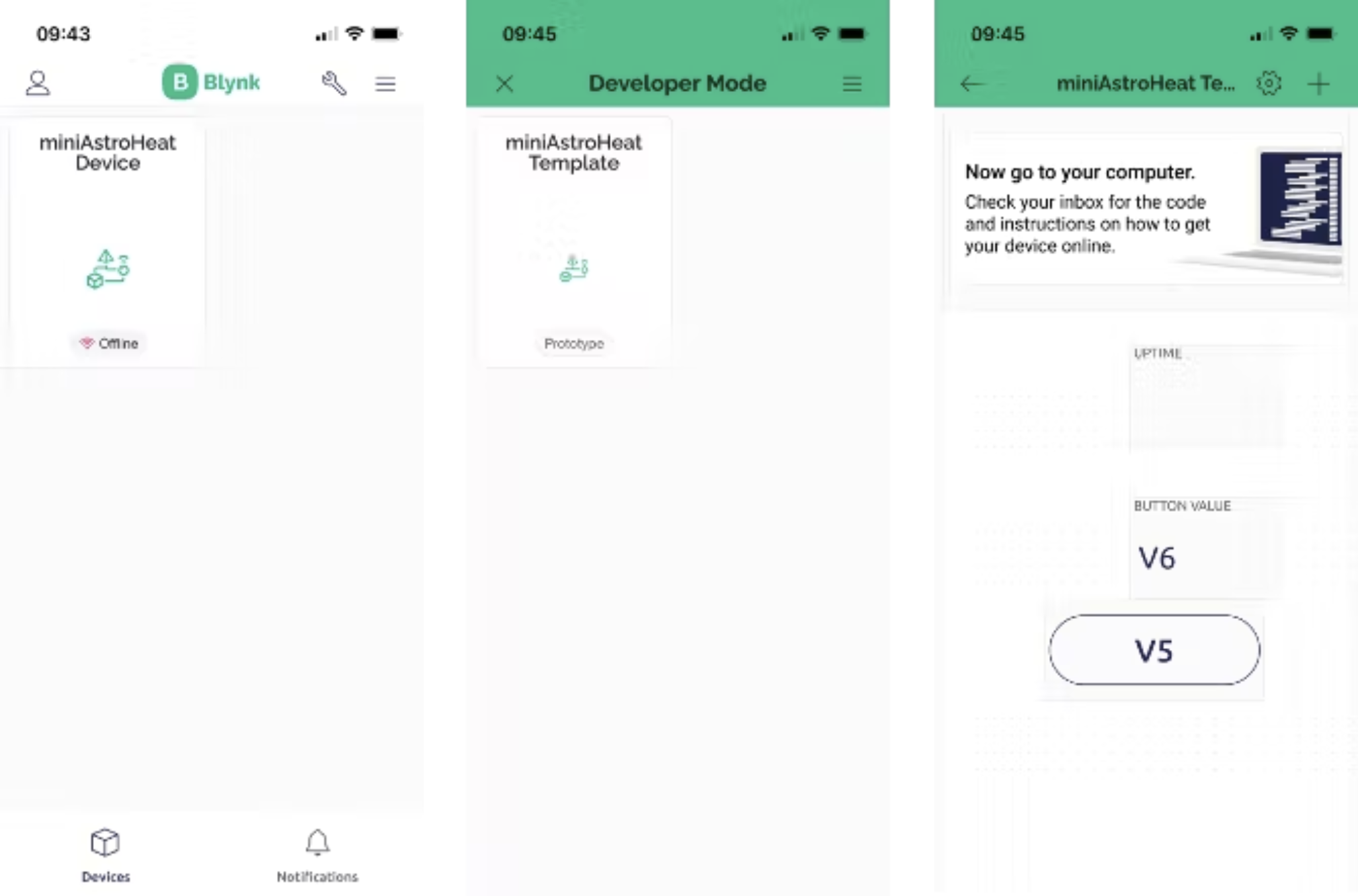
Step 5 – Go to My Devices and copy the firmware configuration.

Click on My Devices in the magnifying glass symbol.

Click on the “Quickstart Device” that have just created.Go to the tab “Device Info” and copy the “firmware configuration” in the black window on the right. As you place the mouse over the firmware configuration window, you will be prompted with a message “Click to copy code”.For security reasons, do not share the firmware configuration for your device.

Step 6 – Copy the firmware configuration in the miniAstroHeat code.

Go back to the Arduino IDE and paste over these 3 lines of code at the beginning of the sketch:

// Template ID, Device Name and Auth Token are provided by the Blynk.Cloud
// See the Device Info tab, or Template settings
#define BLYNK_TEMPLATE_ID "your_template_ID"
#define BLYNK_DEVICE_NAME "your_device_name"
#define BLYNK_AUTH_TOKEN "your_auth_token"

In the code, insert your WiFi credentials:

// Your WiFi credentials.
// Set password to "" for open networks.
char ssid[] = "your_wifi_ssid";
char pass[] = "your_wifi_pass";

Step 7 – Connect the ESP32 microcontroller to your computer.

Connect your ESP32 to your computer with the mini-USB interface and upload the firmware to the ESP32.
For this in Arduino IDE go to Tools-->Board and ensure you choose your ESP32 microcontroller.
In Tools-->Port, ensure that the right port is selected where your USB cable to the ESP32 is connected.
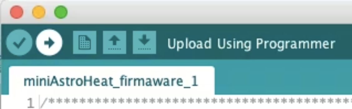
Once everything is OK, then click on the arrow button on the top-left to verify and upload the firmware to ESP32.

Step 8 – Connect the ESP32 microcontroller to your computer.

Next, we'll define the data streams that the ESP32 will use to communicate with the cloud.Go back to Blynk and click on this symbol for “Templates”.

Click on your Quickstart Template and then click on the tab “Datastreams”.Here you can remove any data streams that were automatically generated by Blynk during the Quickstart process. To create new data streams, click on "New Datastream, " select "Virtual Pin, " and designate V5 and V6 as the virtual pins for the manual power control of the heaters. Refer to the image below to properly configure V5.

After creating the Virtual Pin for the Manual Power in the previous step, you will see a list of Datastreams that includes V5. To create V6 for Manual Power 2, simply click on the "copy" button under the "Actions" column.Next, allocate V19 and V20 for transmitting the temperature data from the sensors. To do this, create V19 for Temperature Sensor 1 as shown in the screenshot below. Then, copy V19 to create V20 for Temperature Sensor 2.

Next, allocate a virtual pin as the power mode for the selected mode, either "Dew Automatic" or "Manual". To do this, create a new virtual pin Datastream with the following settings:

Next, allocate the Datastreams for the Ambient Humidity to V16, Ambient Temperature to V17 and Dew Point to V18 Virtual Pins with the following settings:And finally, allocate the Datastreams to display the commanded power to the heaters to V9 and V10 Virtual Pins.

5. Building the miniAstroHeat web-app


To create the miniAstroHeat web app dashboard, navigate to the "Web Dashboard" tab. On the left side, you'll see the Widget Box, which contains the available widgets. Note that the free plan limits you to using only some of the widgets, and up to 30 of them. I'll suggest a dashboard layout, but feel free to arrange the widgets as you see fit for your needs.

Below is an overview of the dashboard. The following section provides a step-by-step guide to help you build this dashboard.

At the top of the Dashboard, I added three "Label" widgets for the Ambient Humidity, Ambient Temperature, and Dew Point Temperature.To add them, simply click and drag them from the Widget Box.Next, we need to link each widget to the datastreams that we previously defined. To do this, simply hover the mouse pointer over the widget and access its settings.In the settings form, allocate each "Label" widget to the corresponding Virtual Pins: 16 for ambient humidity, 17 for ambient temperature, and 18 for dew point temperature.

Next row I will use it to place for the readings of the temperature sensors and a "Switch" widget to change between automatic and manual heating mode.For the sensor's temperature, just do as we did before to setup the Label widget ambient sensor temperature, allocating V19 for Temperature Sensor 1 and V20 for Temperature Sensor 2.Allocate the "Switch" widget to V1 Power Mode as in the screenshot bellow.

Next row I will use it to place the "Gauge" widget to display the commanded power to the heaters. Allocate V9 for power 1 and V10 for power 2.

And on the last row I would place the "Slider" widgets to control the manual power settings, so it can set individually and manually the power for each channel. Allocate Datastream V5 for Manual Power 1 and Datastream V6 for Manual Power 2.

In the Info tab you can change the name of the template to “miniAstroHeat” or any other name you wish. Do not forget to click Save and Apply once you have finished the dashboard design.

6. Building the miniAstroHeat smartphone app


To build the miniAstroHeat app on your mobile device, first download and install the Blynk IoT app from the AppStore (IOS) or Google Play (Android).

To help you building the dashboard for your mobile app, see below the screenshot with an overview of the app design at the end of the process.

Use the same email and password to log in as you did for the web dashboard.To design your app by adding widgets to a template you need to switch to developer mode by clicking on the wrench icon.To design your app by adding widgets to a template you need to switch to developer mode by clicking on the wrench icon. Next, select the miniAstroHeat template.You might see some sample widgets. There are 2 ways of deleting a widget; clicking on the widget and at the bottom of the design form and click on delete, or long-click and drag the widget to the top-right corner, and release over the rubbish bin icon.

To insert a widget in the dashboard, click on the + icon on the top-right corner, scroll down, select Labeled Value and fill the form for Ambient Humidity as in the screenshot bellow. Once you filled all the fields, you can exit by clicking in x icon on the top-left corner. The changes for this widget are saved.

Now, a little trick. Long-click on a widget in the dashboard will allow you to re-size & re-locate the widget, quick copy and quick delete, if you drag it. Let’s see how.

For the Ambient Temperature widget, long-click and drag to the top-left corner and release over the copy icon.A new Labeled Value widget is copied on the dashboard. Just change the name and the datastream as in screenshot bellow.This is a quick way of creating a dashboard for the mobile app.Now you can long-click on the widget to re-size and re-located it to fit the app design.Test it by yourself and do the same for the Dew Point widget.

Repeat the previous step for Sensor 1 Temperature and Sensor 2 Temperature widgets.

Next insert a Button widget, fill the form as per the screenshot. The Button widget shows a design form with 2 tabs: Settings and Design

Next insert a Gauge widget for Power 1 as in the screenshot. Then copy the widget by long-click and dragging it and fill the fields for Power 2. Size them and position them on the dashboard as in the first screenshot at the beginning of this section.

And finally insert a Slider widget for Manual Power 1 command as in the screenshot. Copy the Slider widget and edit the details for Manual Power 2 command. The Slider has also 2 tabs, one for Settings and one for Design.

At this stage you can exit the developer mode and your miniAstroHeat app is done.

7. Power up the system

It is time to power up the system and see it working.

Warning! Remember not to power up the ESP32 from 2 different source inputs simultaneously. 

I recommend for the first tests to power the ESP32 just with the mini-USB.When the miniAstroHeat is in Automatic Dew Point heating mode, the Sliders will display the target temperature for each channel. These target temperatures are calculated based on the current dew point temperature and the system will adjust the commanded power to reach the calculated target temperature, that is set 8 degrees above the Dew Point, preventing the appearance of moisture.The larger the difference between the calculated target temperature and the actual temperature measured by the sensors (below calculated temperature), the more power will applied the miniAstroHeat to the heaters.When the miniAstroHeat is turn to Manual Heating mode, the power applied to the heaters is commanded by the sliders. You can see the amount of power being applied to each heater by looking at the Gauge widgets.

8. Recommendations for the enclosure and installation


To ensure that the miniAstroHeat is safely integrated with your (astro)photography equipment or telescope, it is important to use an appropriate enclosure. A regular plastic enclosure for electronic projects, which can be easily obtained from an online electronics shop or Amazon, is recommended. A size larger than 12cm x 10cm x 4cm will provide ample space for the project. You can refer to the bill of materials for an example.

To attach the components to the enclosure, double-sided adhesive tape or velcro can be used. Waterproof cable glands, like the ones listed in the materials, are recommended to pass the cables through the enclosure walls for the sensors, heaters, and power. Drilling holes in a plastic enclosure for cable glands is easy, and once the cables are passed through, they should be tightened securely to prevent tension on the components. No soldering skills are required for this step, just a screwdriver and cable peeler.